| www.ethanwiner.com - since 1997 |
Mike Pads and Other Small Gadgets
by Ethan Winer
This article first appeared in the June 1984 issue of Recording-engineer/producer magazine.
Read all about
Ethan's |
In past issues of R-e/p I have presented a variety of construction
projects, and some have been fairly complex. But it is the simpler problems most of us
deal with every day. With that in mind I have compiled an assortment of little projects,
and most can be built in an hour or two. These "miniature marvels" are the
subject of this month's article.
What got me interested in building these diminutive devices is the S3FM connector assembly made by Switchcraft. The S3FM is simply a 3.5-inch tube fitted with a male XLR at one end and a female at the other, with enough room in the middle to build a mike pad, low-end rolloff network, polarity reverser, or any number of other useful little gadgets. Related to the S3FM is the 380AP1 series of XLR to 1/4-inch audio adapters. The metal sleeves on these adapters are smaller than the S3FM, though with care you can squeeze a phantom-powered active direct box into one. Placed at the end of a standard mike cord, you can plug it directly into a bass or synthesizer without the usual mess of cables, adapters, and clutter. [You can buy S3FM adapters on THIS page at Markertek. Other models are listed at the Switchcraft web site.]
Of course, there's no reason to limit the discussion to gadgets that can be shoehorned into a miniature connector. So along with the pads, rolloffs, and direct box, I will also show how to build a battery-powered phantom supply and a mike/line level test oscillator. That last one is handy when you're alone at a remote recording session and need to verify that the mike cables and console or recorder inputs are functioning properly. We'll start at the beginning with the easier items first.
PADS AND ROLLOFF CIRCUITS
 The balanced
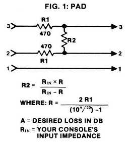
mike pad shown in Figure 1 is about as basic a circuit as you're likely to encounter. But
finding the optimum resistor values can be a challenge for the beginner, and a time
consuming nuisance for the more advanced. The computer is a handy friend to have around,
and the accompanying sidebar describes my Universal Audio Network Program linked
below which calculates component values for all the various pad and rolloff circuits
described in this article. It's not clear in this reproduction, but the line of the
formula is:
The balanced
mike pad shown in Figure 1 is about as basic a circuit as you're likely to encounter. But
finding the optimum resistor values can be a challenge for the beginner, and a time
consuming nuisance for the more advanced. The computer is a handy friend to have around,
and the accompanying sidebar describes my Universal Audio Network Program linked
below which calculates component values for all the various pad and rolloff circuits
described in this article. It's not clear in this reproduction, but the line of the
formula is:
(10 ^ (A/20)) - 1
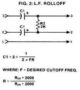
Figure 2 shows the same general configuration, except this circuit yields a low-end rolloff beginning at a frequency dictated by the resistor and capacitor values. Notice that the designation "R1" does not appear in this diagram. The same component numbering is used throughout the figures to make the formulas easier to understand and the drawings and Audio Network program more consistent. Also note that the low-cut circuit in Figure 2 will not pass phantom power.
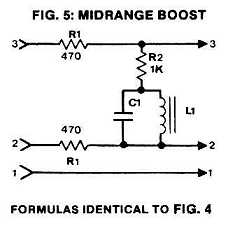
Transposing the capacitors and resistor gives a high-frequency loss
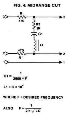
(Figure 3), while adding an inductor allows tampering with the midrange response for
boosting presence or controlling sibilance (Figures 4 and 5). Two sources for miniature
audio inductors are Mouser Electronics
and DigiKey. Although many electronic
shops carry some assortment of coils, they rarely stock values larger than 1 mH.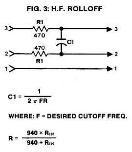
One problem with inductors is their inherent series resistance, which is inevitable due to the wire they're made from. The smaller (physically) a given inductor is built, the higher the resistance since the wire must be a smaller diameter. The Mouser 43LH and 43LJ series inductors minimize this by winding the wire around a ferrite core. For high-level inductors such as a speaker crossover, iron or ferrite cores are avoided because the core material can overload or "saturate" just like magnetic recording tape. But at these low currents the ferrous core does a great job of increasing the inductance without requiring as many turns of wire, which keeps the series resistance relatively low. Also, these coils are encapsulated into a rugged phenolic case which eliminates the danger of damaging the hair-thin wires during assembly.
For the midrange networks shown in this article you can expect to alter the response by about 4 or 5 dB, though this can be varied by adjusting R2 up or down in value. With the high- and low-end rolloffs, the cutoff slope is 6 dB. per octave beyond the chosen frequency. This rolloff rate is hard to change because additional capacitors and resistors would be needed. That not only complicates the design, but also reduces the signal level overall.
 While we're on the
subject of high- and low-end rolloffs, I'll add my own opinion about what I consider
confusing nomenclature. Many audio equipment makers label a low-end roll-off switch as
being "high-pass," and the high-frequency cut switch as "low-pass."
Now I realize these terms have roots in traditional engineering, but I believe these
labels are misleading when applied to audio equipment. If a switch affects the low
frequencies it should be called a "low something," and when it influences the
highs a "high something." Doesn't that make more sense?
While we're on the
subject of high- and low-end rolloffs, I'll add my own opinion about what I consider
confusing nomenclature. Many audio equipment makers label a low-end roll-off switch as
being "high-pass," and the high-frequency cut switch as "low-pass."
Now I realize these terms have roots in traditional engineering, but I believe these
labels are misleading when applied to audio equipment. If a switch affects the low
frequencies it should be called a "low something," and when it influences the
highs a "high something." Doesn't that make more sense?
Closely related to mike pads are attenuators that let you patch a guitar amplifier's speaker output directly into a mixing console. Most guitar players I know would sooner cut off their left hand than use a direct box, and an amp pad lets you retain most of the amplifier's sound while eliminating leakage into nearby microphones. For this application simply use the circuit in Figure 1 - balanced input and all - though you must alter the resistor values somewhat to accommodate the higher input voltage. If you use 10K for both R1 resistors and 100 Ohms for R2, the pad can handle input levels up to 100 Volts before the resistors get warm. One important note: Check the amplifier's ground polarity before you connect it to your board, or at least turn your monitors way down to avoid a loud blast of hum.
CONSTRUCTION TIPS
 With space at a premium
inside these tiny tubes, you should use the smallest components you can find. For
mike-level signals you can use 1/8-watt resistors, though these are less common than the
standard 1/4-watt type. Again, Mouser and DigiKey carry these and many other electronic
components.
With space at a premium
inside these tiny tubes, you should use the smallest components you can find. For
mike-level signals you can use 1/8-watt resistors, though these are less common than the
standard 1/4-watt type. Again, Mouser and DigiKey carry these and many other electronic
components.
Another space saver when building mike-level circuits is to use low-voltage capacitors. When the component values are large, such as the low-frequency rolloff, tantalum capacitors are the best choice and you may be able to find ultra-miniature types rated as low as 6 or even 3 Volts. Tantalums cost more than standard electrolytics, but they are smaller and generally higher quality.
You should use shrink-fit sleeving over all of the components or otherwise ensure that the components don't short out to one another. The S3FM comes with a plastic-coated cardboard tube that lines the inside of the case, and this prevents any wires from touching the grounded case. I prefer clear shrink tubing since it lets you see what parts are inside - a definite advantage three years from now if you have to take it apart for repair or just to see what's in there. Avoid black electrical tape for insulation; not only can't you see through it, but after a while it turns into a gooey, sticky mess that's difficult to unwrap. I recommend that you draw the schematic on a small piece of paper, and roll it up to serve as the outer insulation.
 To make the
assembly truly secure if you don't care that it can't be opened later, you can encapsulate
the whole device in potting compound. Two-part epoxy mixture is ideal, with the following
precautions in mind: First, you must mix the two parts in exactly equal amounts or the
epoxy may never dry completely. Second, it is possible that some liquid will run out the
bottom while you're pouring it into the top. Use a liberal coating of Vaseline around the
base of the connector to prevent that. Instead of standard potting compound, you can
optionally use RTV. Available from electronics and hardware stores, RTV is a clear uncured
rubber that dries in about 24 hours. Although it never fully hardens like epoxy, it
becomes quite firm. In fact, that can be an advantage since it provides shock isolation
for the components. Also, RTV doesn't run when you apply it so it's less likely to get on
the connector contacts.
To make the
assembly truly secure if you don't care that it can't be opened later, you can encapsulate
the whole device in potting compound. Two-part epoxy mixture is ideal, with the following
precautions in mind: First, you must mix the two parts in exactly equal amounts or the
epoxy may never dry completely. Second, it is possible that some liquid will run out the
bottom while you're pouring it into the top. Use a liberal coating of Vaseline around the
base of the connector to prevent that. Instead of standard potting compound, you can
optionally use RTV. Available from electronics and hardware stores, RTV is a clear uncured
rubber that dries in about 24 hours. Although it never fully hardens like epoxy, it
becomes quite firm. In fact, that can be an advantage since it provides shock isolation
for the components. Also, RTV doesn't run when you apply it so it's less likely to get on
the connector contacts.
PHANTOM POWER SUPPLY
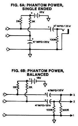
Another simple but useful goody is the portable, battery-powered phantom supply for condenser microphones shown in Figures 6A and 6B. This is useful for remote recording when you plug a pair of mikes plugged directly into a tape recorder. Many AKG brand microphones can run on as little as 15 Volts, which can be provided by a pair of standard 9 Volt batteries. But most microphones need the full 48 Volts that is standard for phantom power.
For mikes requiring a 48 Volt phantom supply you can use a pair of miniature 22.5 Volt camera batteries available at Radio Shack and camera stores. This is the same type of battery used by Neumann in their U-87 microphones. While they won't last as long as the 9 Volt types, they can provide enough juice to get through several concerts. Note that to power an AKG mike from less than 48 Volts you must reduce the resistors that connect the batteries to the mike line. Normally two 6.8K resistors are used with 48 Volts, but when using 18 Volts (two 9 Volt batteries in series) these resistors should each be 2K. For either value use 1% tolerance resistors to maintain the signal balance and minimize hum and noise pickup.
 For the 48 Volt
version, besides using 6.8K resistors you must also increase the voltage rating of the 47
uF. electrolytic caps. A 50 Volt rating is adequate, but for higher reliability I
recommend 63 Volts or more. Also, if you plan to power two mikes at a time you should use
two separate battery assemblies. Not only will this extend the battery life, it also
minimizes any chance of crosstalk. If you prefer to use one set of batteries for both
mikes, at least wire a 47 uF. capacitor across the battery to keep the battery impedance
low. With fresh batteries it is unlikely you will get any crosstalk, but as a battery ages
its output impedance rises. The added capacitor keeps the impedance low at audio
frequencies.
For the 48 Volt
version, besides using 6.8K resistors you must also increase the voltage rating of the 47
uF. electrolytic caps. A 50 Volt rating is adequate, but for higher reliability I
recommend 63 Volts or more. Also, if you plan to power two mikes at a time you should use
two separate battery assemblies. Not only will this extend the battery life, it also
minimizes any chance of crosstalk. If you prefer to use one set of batteries for both
mikes, at least wire a 47 uF. capacitor across the battery to keep the battery impedance
low. With fresh batteries it is unlikely you will get any crosstalk, but as a battery ages
its output impedance rises. The added capacitor keeps the impedance low at audio
frequencies.
TONE GENERATOR
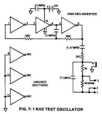
If you've ever had to track down a broken mike cable you'll appreciate this tiny tone generator that can be plugged into one end of the cord. If sound comes out the other end you know the cord is okay, though this tester won't tell if the polarity is reversed. Another use for a tone generator is troubleshooting a console via the patch panel. If nothing seems to be getting through channel 12, for example, insert the line-level output of the tester into each of channel 12's insert points starting with the last. Work towards the input, and when the 1 KHz. tone disappears you'll know where in the chain the signal is getting lost.
This tone generator circuit is based on a CMOS inverter package such as the 4069 or the 74C04, and it will run for many hours on one 9 Volt battery. Of course, CMOS ICs are meant for digital logic circuits, but they're just as useful at audio frequencies. Install two output jacks - one for line-level and one for mike-level as shown in Figure 7 - and be sure to wire the XLR connector pins 1-3 exactly as shown. Even though the test signal is sent down only one of the two hot leads, the other is used as an "active" return for mike inputs that are transformer coupled. The 4069 IC contains six individual inverters, but you need only three. As with any CMOS device, always connect the unused inputs either to ground or the power supply.
ACTIVE DIRECT BOX
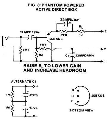 The direct box shown
in Figure 8 is based on the 2SB737S transistor which features extremely low noise and very
high gain. Although the audio output from this circuit is single-ended, the low output
impedance prevents picking up noise or hum in all but the most severe environments. Like
most direct boxes the circuit has a signal level loss, not gain, from input to output.
This is because a phantom supply simply cannot provide enough current to drive a low
impedance mike input at line levels, which happens when feeding directly from a
synthesizer or other high-output instrument. [This is not an issue with modern mike inputs
that have no input transformer.]
The direct box shown
in Figure 8 is based on the 2SB737S transistor which features extremely low noise and very
high gain. Although the audio output from this circuit is single-ended, the low output
impedance prevents picking up noise or hum in all but the most severe environments. Like
most direct boxes the circuit has a signal level loss, not gain, from input to output.
This is because a phantom supply simply cannot provide enough current to drive a low
impedance mike input at line levels, which happens when feeding directly from a
synthesizer or other high-output instrument. [This is not an issue with modern mike inputs
that have no input transformer.]
The gain or loss is adjusted by changing the value of RL, with higher resistance giving less gain. If you have a high-impedance mike input and prefer no signal loss you can replace this resistor with a wire. You can also reduce the value of the 22 uF. tantalum caps to 1 uF. or less, but only when driving a high-impedance input! In fact, if your mike inputs have an input impedance less than 1K you may need to increase the 22 uF. capacitors. If you can't find capacitors that large in value and with a high enough voltage rating, use two larger capacitors in series as shown in the schematic. The 1M resistors ensure an equal DC voltage across each capacitor.
When this article was written the 2SB737S transistor was as hard to find as my Uncle Irving's teeth. Other high gain PNP transistors such as the 2N4403 or the 2N3906 are fine, but you should buy a half-dozen and select those with the lowest audible noise.
SIDEBAR: A BASIC Program to Calculate Filter and Attenuator Component Values
If you follow the formulas in the Audio Network program available for download below, you'll notice a departure from traditional design. In the early days of audio most designers matched source and terminating impedances. So if a given microphone had an output impedance of, say, 200 Ohms, then the preamplifier circuit it fed would also have a 200-Ohm input impedance. Later, audio engineers discovered that while impedance matching still makes sense for RF circuits and antennas, a microphone's signal-to-noise ratio is improved when it feeds an impedance much higher than its own. These points were discussed in depth by Paul Buff in his article describing the design and development of the Valley People Transamp mike pre-amp in the December 1977 issue of R-e/p magazine.
Other benefits are attributed to a higher terminating impedance, such as reduced distortion and increased frequency response, so it was an easy decision to design these pads and rolloffs for a minimum console mike input impedance of 1,000 Ohms. This also simplifies the Audio Network program because the number of variables is reduced.
Since this program reports exact resistor and capacitor values, you'll have to pick from the standard values available and possibly combine two components to get the value needed. For the midrange boost and cut circuits you can pick the next smaller standard inductor value, and then choose the next larger capacitor to keep the center frequency about the same.
You can download my Audio Network program that's ready to run in either DOS or Windows. Click HERE to download NETWORKS.ZIP (415K) which contains both the BASIC source and two compiled .EXE versions of the program:
Added February 23, 2018: Thanks to John Goad for creating a version of this program compatible with 32-bit and 64-bit Windows using the QB64 compiler. He tested it with 64-bit Windows 10 and 32-bit Windows 7, and it runs under 64-bit Windows 7 Professional on my computer. The Zip file linked above contains both the original DOS executable and this new Windows version. Beware that anti-virus programs might think this program is a virus and delete the file when you go to run it. That's what AVG anti-virus did! But I promise this program works as advertised.
Entire contents of this web site Copyright © 1997- by Ethan Winer. All rights reserved.