| www.ethanwiner.com - since 1997 |
Audio Filters - Theory and Practice
by Ethan Winer
This article first appeared in the August 1981 issue of Recording-engineer/producer magazine.
Read all about
Ethan's |
PART 1: FILTER THEORY
In a previous article I explained that capacitors are essentially frequency-dependant resistors. This capacitive resistance, more properly called reactance, is at the heart of all active audio filters. Before getting down to the nuts and bolts, let's first review some filter basics using terms a recording engineer can readily understand.
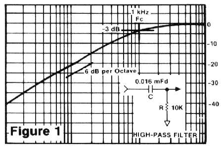
One type of filter is the high-pass (or low-cut) shown schematically in Figure 1, along with the resultant frequency response. At some specified frequency, the capacitor's impedance is equal to that of the resistor, and it is here that the response will be 3 dB. down. If this frequency is 1 KHz., then the filter is referred to as a 1 KHz. high-pass. Really, what could be easier? As the applied frequency is lowered, the output level continues to drop at a rate of 6 dB. per octave, or 20 dB. per decade (factor of ten). Obviously, filters can be built with sharper cutoffs, but to do this you must cascade several stages. In the Popping P filter described later in this article, two stages are used, creating a 12 dB. per octave roll-off.
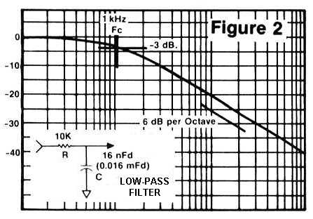
The low-pass filter, shown in Figure 2, is constructed by transposing the resistor and capacitor. Everything previously stated still applies, only now the output level goes down as the input frequency is raised, instead of as it is lowered.
A third kind of filter is the band-pass shown in Figure 3. The classic implementation is with a capacitor and inductor, as shown. In this case, a range of frequencies is allowed to pass through the filter, and these are centered around - you guessed it - the center frequency. This point of minimum attenuation occurs at a frequency for which the inductor's impedance equals that of the capacitor, and can be achieved with a variety of values. That is, if you halve the capacitance but then double the inductance, the frequency remains the same even though the ratio has been altered.
On a parametric equalizer, there is a control for varying bandwidth, or how far from the center frequency the boost and cut action extends. When boosting highs on a broad setting, the effect is smooth and uncolored. When using the narrow settings, however, the sound is very resonant like a wah-wah or synthesizer filter.
Although the bandwidth in this simple circuit can be changed by varying the ratio of the inductor to the capacitor, a much better approach is to use an op-amp to provide positive feedback. Where negative feedback is used in circuits to lower distortion and flatten response, positive feedback reinforces the band-pass action giving the capability for extremely narrow bandwidths. In the active filters shown later in this article, only capacitors are employed, in a combination high-pass/low-pass configuration. Studio talk refers to bandwidth in terms of octaves or parts of an octave. Design engineers, on the other hand, call this filter parameter Q, which stands for Quality.
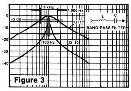
A typical octave graphic equalizer has a Q of 1 on each of its control bands. Notch filters used for eliminating hum might need a Q as high as 100 if adjacent frequencies are to be left untouched. The filters described later in this article to isolate different hum frequencies have a Q of 10. Or more specifically, the center frequency is 10 times the number of Hz. contained within the passband (those frequencies attenuated by an amount less than 3 dB.) This means that for a 1 KHz. filter, 100 cycles are encompassed between the -3 dB. points, as shown in the illustration. For a Q of 50, a bandwidth of only 20 cycles are contained within these bounds.
It is important to point out that in a simple active band-pass filter, even though the bandwidth may be very narrow at the tuning point, eventually the response falls off at the usual 6 dB. per octave rate as the feedback contributes less and less. A Q of 10 is sufficient for our purposes to effectively isolate each frequency, and yet not so severe as to require the use of 1% tolerance components as would a higher-Q circuit.
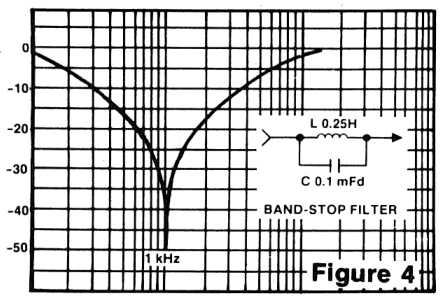
Similar to the band-pass is the band-stop, which is also known as a notch filter. Again, although a coil and capacitor can be used as shown in Figure 4, most modern versions use an active design with capacitors and resistors only. Naturally, the terms used for the band-pass filter apply in this case, and feedback continues to take the credit for high Q.
In a future article I will cover active filters in greater depth, and provide "cookbook" style formulas so you can design these circuits to suit your own needs. In the meanwhile, the following pair of books may be of interest for the reader wanting to find out more about filter design:
1. Audio IC Op-Amp Applications, by W.G. Jung. Howard W. Sams & Co., 1978.
2. IC Op-Amp Cookbook, by W.G. Jung. Howard W. Sams & Co., 1977.
PART 2: FILTER CONSTRUCTION PROJECTS: AN ANTI-POPPING FILTER
It was strictly amateur night as I rewound the tape for the twentieth time, and the lead singer tried "just one more take." Well, he finally did get a good one - that is, in tune at least most of the time - but the only problem was this big, fat popping P right in the middle of a verse. Out of time and out of money (not to mention out of talent), the group had little choice but to proceed to the mix, popping P and all.
I have always had it in the back of my mind to someday make the removal of popping Ps a priority pet project. (Sorry.) After all, there are de-essers for controlling excess sibilance; why not a gadget that could detect and filter out these problem Ps? A limiter is unacceptable - you just get an enormous dropout - and while a low-cut filter can help in some cases, you'd have to make it pretty darn thin sounding to eliminate a really bad pop. Popping P's have been with us for as long as there have been microphones, and I've heard from nobody that has come up with a satisfactory solution to the problem of removing them from a track after the fact.
THE SOLUTION
So I'm thinking about all of this as I'm starting the mixdown, when an idea suddenly came to me: Why not try shelving the lows, but only for the duration of the pop? So, when I got to the offending place in the verse, I slammed the low-cut EQ knob to -15 dB., then quickly brought it back to flat. The popping disappeared completely, and all of those present at the remix session agreed that the EQ was inaudible, just so long as I brought the knob back to flat fast enough. At last, I had found an effective method; now it simply remained to be automated. The result is shown in Figure 5. [These days you could bring the vocal track into an audio editor program, select just that part of the track with the popping P, and apply a low frequency shelf cut filter. - EW, 7/30/99]
The heart of this device is a low-cut filter, only this one can be activated automatically, on command from the pop detector. Identifying the plosive is not too difficult; all we need to look for is significant low-frequency energy. When a pop is detected, the filter is instantly engaged. Then the low-end response fades back up to normal over a period of a few tenths of a second. This single-timed release approach eliminates the distortion that is usually associated with a combination of fast release times and low-frequency signals. Needless to say, it is essential that the response return to normal immediately following the offending P, if the filtering is to remain unobtrusive.
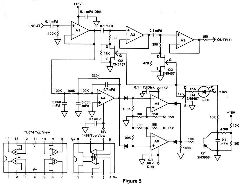
Referring to the schematic shown in Figure 5, amplifier Al is used at unity gain solely to isolate the filter and detector inputs from the outside world. This is important because most active filters should be fed from a very low source impedance. Were the input buffer not included, performance of the filters could vary depending on the output impedance of the preceding device. The actual low-cut filtering is accomplished by the 0.1 uF. capacitors in conjunction with the 390 ohm resistors. Amplifiers A2 and A3 are also used for isolation, but in this case when coming out of the filters.
Automatic operation is realized by the 2N5457 FET's voltage-controlled resistance. When a negative voltage is applied to the gate, the resistance between source and drain is high. But when this voltage is removed, the FET's internal resistance drops dramatically. This then causes the 390 ohm resistors to become essentially grounded, creating a severe reduction in low-end response. (This filter is essentially the same as Figure 1.) A third FET, Q4, is optional, and it drives an LED to indicate activation of the de-pop process.
IC op-amp A4 and its associated components comprise a 50 Hz. low-pass filter with an 18 dB. per octave cutoff slope. This steep filtering action is required to ensure that only a popping P will trigger the unit. The filter output is then sent to a pair of level detectors - A5 and A6 - one to sense each polarity. If the signal below 50 Hz. ever reaches 0.7 Volts in either direction, one of these comparators will switch and energize Q1.
Although A5 and A6 are conventional op-amps, they are operated without any negative feedback yielding an extremely high gain. Therefore, the output doesn't vary as with a normal linear amplifier - it is either full positive or full negative. Hence, an input voltage can be compared to a reference, with even the tiniest difference in level being amplified essentially to infinity. As a general rule of thumb when using comparators, if the plus input is more positive than the negative, the output is full positive. And when the negative input is more positive, the output will be negative.
The FET gates and the 0.1 uF. release capacitor are normally held at 7.5 Volts by the 10k voltage-divider network. When either comparator switches, Q1 is activated and instantly discharges the 0.1 uF. capacitor and engages the low-cut filter. The moment the pop goes away Q1 is turned off, allowing the capacitor to recharge thus restoring normal response. It may be necessary to experiment with the value of the 470k release resistor if you plan to use a different type of FET. Also, a P-channel device requires connecting the 10K network to V+ instead of V-.
Op-amps Al through A4 should be high performance types, such as the TLO74 quad. A 1458 dual package is sufficient for the comparators, and nearly any PNP transistor will work as Q1. You might as well use good quality mylar capacitors throughout, since the slight increase in price is more than offset by the improved stability they offer. All diodes are small signal types such as the 1N914 or 1N4148, except of course the LED. And while it is not always shown, every IC must have a 0.1 uF. disk capacitor connected between ground and each of its power supply pins. These caps should be located as close to the op-amps as possible.
HUM INJECTOR / FILTER
Another difficult problem exists when trying to filter out power-line hum, especially in the presence of music. Often there is more than one offending frequency present, requiring several notch filters to be cascaded. And if a musical note happens to be near one of those frequencies, then the note will be removed as well. Let's face it, it's impossible to filter out 60 Hz. hum without affecting a bass note at exactly the same frequency, isn't it? The answer is No, and what's more, the "filter" shown in Figure 6 is so slick you don't even have to pass the signal through it, thereby eliminating any chance of degrading the audio quality.
But before you conclude I'm crazy, consider how a conventional notch filter works. The audio signal is sent through a phase shift circuit that provides 180 degrees of shift at some specified frequency, relative to the input. When the input and output of this circuit are combined, a null in the response is created at that frequency. The phase-shifted signal is used to oppose the original input, and if the two levels are exactly equal the result is complete cancellation.
We've all seen those brain teasers where because of preconditioned thinking, you tend to overlook an otherwise obvious solution to a problem. In the case of canceling hum, who says the opposing frequency must be derived from the original signal? If we instead use a sample of the actual power line as the hum-bucking medium, we can exactly balance any hum in the program while allowing the music to remain untouched. The only drawback to this approach is that it must be done in real time, so that the hum source and the hum cure will be synchronized. This means that it won't work on tracks already recorded, but then why save for later what could be fixed now? Especially when it's so easy to do. Also, I suspect the biggest need for a device like this is in live sound reinforcement where there often isn't time to track down the source of hum.
Now let's look at the actual hum filter circuit, whose schematic is shown in Figure 6. When I first began this project I analyzed the residual hum present in various pieces of outboard equipment. By sweeping the frequency on a parametric equalizer, it was easy to audibly determine the major hum components. Since most audio devices use full-wave rectification in their power supplies, it is not surprising that 120 Hz. was the most predominant frequency. Also present, of course, were 60 Hz., 180 Hz., and 300 Hz. - the fundamental, third, and fifth harmonics. The higher I swept the equalizer, the more the harmonics diminished, indicating that four stages would probably be sufficient.
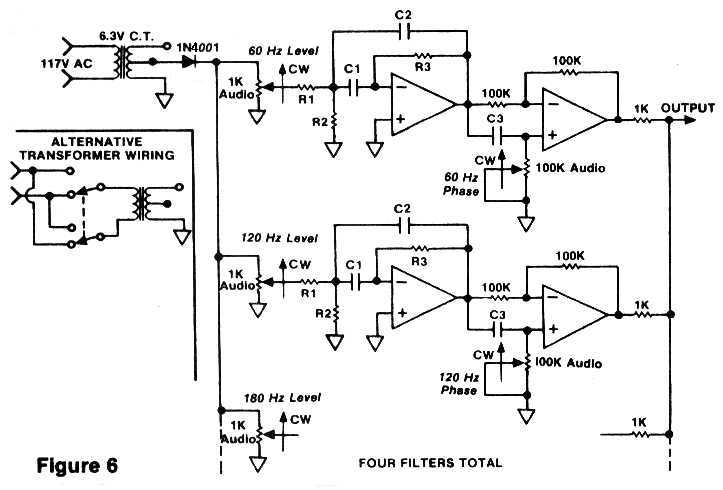
Since the audio signal does not pass through this filter, some other method is needed to create the hum-canceling frequencies. In this case, a 6.3 Volt center-tapped power transformer is used to furnish the 60 Hz. signal, though we still need to generate the harmonics. The necessary distortion is provided here by the 1N4001 diode. Four separate high-Q band-pass filters are then used to isolate each of the desired frequencies, and the component values for these filters are listed in Table 1. (Values for use with 50 Hz. power systems are shown in Table 2.) A variable phase shift circuit is also provided to ensure maximum rejection capability of the hum. (This is particularly important when equalizers or other devices that affect phase are in the audio path.) The filtered and phase shifted hum frequencies are finally combined through a series of 1K resistors at the Output, and the composite signal is sent to the console to be mixed with the program material.
TABLE 1: Component Values for 60 Hz. Hum Filter
| Filter Hz. | R1 | R2 | R3 | C1 & C2 | C3 |
| 60 | 270K | 1.2K | 560K | 0.1 uF. | 0.27 uF. |
| 120 | 150K | 680 ohm | 270K | 0.1 uF. | 0.15 uF. |
| 180 | 82K | 430 ohm | 180K | 0.1 uF. | 0.1 uF. |
| 300 | 56K | 270 ohm | l00K | 0.1 uF. | 0.068 uF. |
TABLE 2: Component Values for 50 Hz. Hum Filter
| Filter Hz. | R1 | R2 | R3 | C1 & C2 | C3 |
| 50 | 330K | 1.6K | 620K | 0.1 uF. | 0.33 uF. |
| 100 | 160K | 820 ohm | 300K | 0.1 uF. | 0.18 uF. |
| 150 | 91K | 560 ohm | 200K | 0.1 uF. | 0.12 uF. |
| 250 | 68K | 330 ohm | 120K | 0.1 uF. | 0.1 uF. |
TABLE NOTES: All filter components should be 5% tolerance, although the value of phase shift capacitor C3 is less critical. For C3 you can use the next larger size if the specified value is not available.
To save circuitry only one stage, or 0-180 degrees, is used. Therefore it may be necessary to reverse the plug in the wall outlet. Or, better yet, you could use a DPDT power switch with a center-off position, wired as shown in the diagram inset. This scheme is commonly used for switching the polarity on guitar and bass amplifiers to minimize hum.
Once the unit is built and working, adjustment of the controls for hum elimination is relatively straight-forward: First, turn all four level controls and four phase controls to full counter-clockwise (minimum) setting. Then, just to familiarize yourself with the sound of each hum element that you will be nulling out, advance the level controls one by one noting the difference, and then return them all to off. Since 120 Hz. will probably be the worst offender, start by increasing the level for that frequency very slowly, until the 120 Hz. hum component goes down in level, leaving the knob at the optimum point. The 120 Hz phase control should also be adjusted for minimum hum at that frequency, then go back to the level pot and finish the job. You should be able to completely eliminate all hum at this frequency in only two or three steps. If the hum only goes up in level no matter how you set the controls, reverse the polarity switch on the wall plug and repeat the above steps. Next, adjust the 60 Hz. frequency, followed by 180 Hz. and 300 Hz. until you are satisfied that these frequencies have been completely eliminated from the program source.
Once you use this device a few times, it will be easy to complete the entire process in under a minute or so. Also, the unit puts out a healthy signal, so it should be mixed in with the program at a very low volume. Otherwise, you'll find yourself working the hum filter's level pots near their minimum range, making adjustment more difficult than it should be.
Entire contents of this web site Copyright © 1997- by Ethan Winer. All rights reserved.